Electrical System Overview – Lessons from Zenith to Orca
By Avionics Team | April 2, 2025
Lessons Learned:
Another vehicle, another electrical system. With SUAS 2025 competition rules heavily favouring a fixed wing platform, it was time to start fresh. While Zenith is now retired, there were many lessons learned from that design cycle that we applied in the creation of Orca.
Overspecing for Robustness:
At competition last year, there was an incident where a wind gust disrupted Zenith during flight. To stabilize mid air, we had to burn extra battery power. This cut down our total flight time, thus limiting our ability to score points by completing more objectives.
This year we made sure to overspec our electrical systems so that we have enough to complete the mission objectives and more.
Physical Layout:
As is natural during engineering competitions, things went wrong. Unfortunately, Zenith’s design made it so the avionics were not easy to access; substantial disassembly was required to access key components. This added complexity made troubleshooting more challenging.
This year we made sure to have all critical systems easily accessible so that testing, integration, and troubleshooting can be made more efficient.
Component Quality:
For engineering projects, budget is a huge consideration. With Zenith, we opted to go for a mid level flight controller. This ultimately cost us when we were attempting an autonomous landing. In an ideal landing, the vehicle will slow down as it approaches the ground. Zenith did not slow down in time, thus damaging much of its frame. After diagnosis, we found that the flight controller had poor altitude readings from its IMUs.
This year we made sure to spend extra where it matters. It’s better to spend more during development so that you don’t have to spend extra doing repairs.
What’s Changed:
The main blocks of our system architecture remain unchanged. The main evolution of our avionics system is a new Custom GCS that works in tandem with Mission Planner.
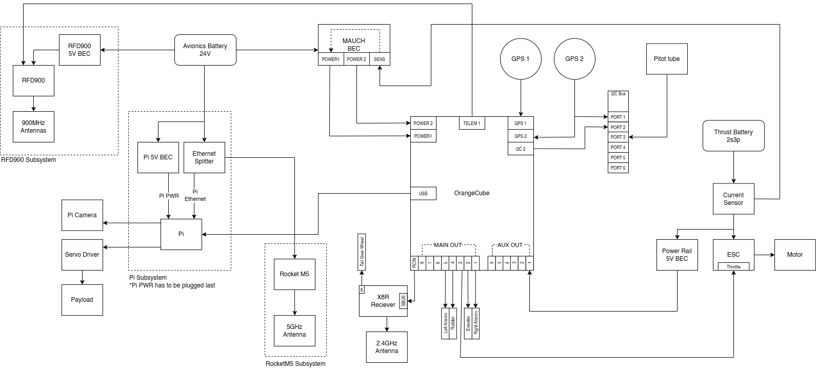
We have two separate batteries powering all of our systems, an avionics battery and thrust batteries. The avionics battery powers the majority of the avionics hardware, including the:
- RFD900: A long range 900 MHz radio modem facilitating communication between Mission Planner and the Cube Orange
- Raspberry Pi: The mission computer that facilitates the capture, processing, and calculations for competition objectives
- Rocket M5: A 5 GHz radio to communicate data from the Raspberry Pi to the new Custom GCS
- Cube Orange: The flight controller that stabilizes flight while executing autonomous operations
- X8R Receiver: A 2.4 GHz receiver that receives manual control from the pilot’s handheld remote control
The thrust batteries are true to the name, powering the few components related to flight:
- ESC (Electronic Speed Controller): Converts flight commands from the remote control or Cube Orange into high power signals to spin the motor and control throttle
- Control Surfaces: Includes the ailerons, rudder, and elevator for maneuvering the aircraft
Moving Forward:
Given Orca’s tight development window, there were a few nice-to-have features that didn’t quite make it into the final designs. Most significant is the implementation of a custom power management PCB. While the new electrical design is leaps and bounds ahead of old designs in terms of accessibility, with how much hardware we have in the fuselage, there is still some overcrowding with wiring.
On top of this, with the many different systems to power, we have 5 different Battery Eliminator Circuits (BECs) to convert 24 V power to usable 5 V power. Including power conversion on the custom power management PCB would allow us to simplify our overall architecture; the many different BECs could be consolidated to just one component.